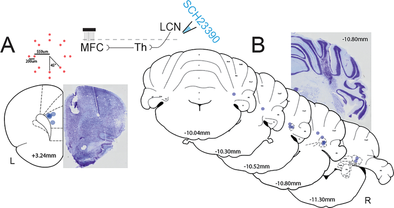
Fig 2: Histological reconstruction of LCN infusion cannulae and MFC electrode arrays.
A) Central placement of MFC electrode arrays (blue dots, N=5) with distance from bregma and example thionin-stained section. Inset top left: top-down view diagram of custom electrode geometry with measurements from center, red dots indicate individual channels. Inset top middle: circuit diagram illustrating thalamic relay from LCN D1DRs to the MFC. B) LCN cannula placements (blue dots, N=12) with distance from bregma ranging from −10.04mm to −11.30mm. Example thionin-stained section with LCN cannula tract at −10.80mm from bregma. Coronal MFC and cerebellar templates adapted from Paxinos & Watson (2007).

