
FIG. 4.
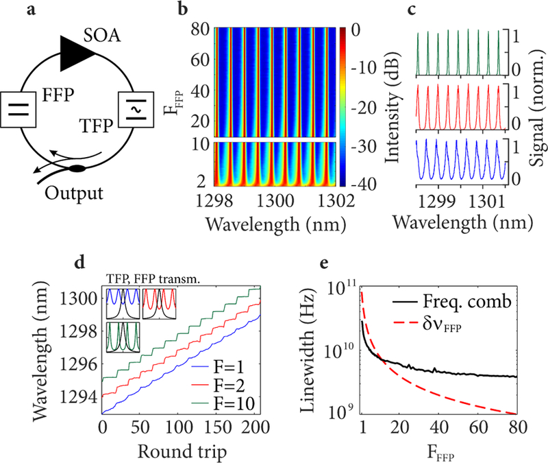
(a) Schematic of a frequency stepped, external cavity, frequency comb laser used for simulations. (b) Simulated optical spectra of the stepped frequency comb laser output with different values of the FFP finesse. (c) Three selected optical spectra for a FFP finesse of 1 (blue), 2 (red) and 10 (green). (d) Simulated instantaneous wavelength per roundtrip (1 round trip = 15 ns) at the laser output for three values of the FFP finesse. Insets in (d) show linear plots of the FFP and TFP (FWHM = 40 GHz ) transmission profiles (spanning ±150 GHz ) for FFFP =1, 2, 10. (e) Simulated frequency comb instantaneous linewidth at the laser output for increasing FFP finesse (solid black line). The red, dashed line depicts the FFP bandwidth. FFP FSR was 80 GHz, TFP linewidth was 40 GHz, sweep speed was 2 nm/µs.