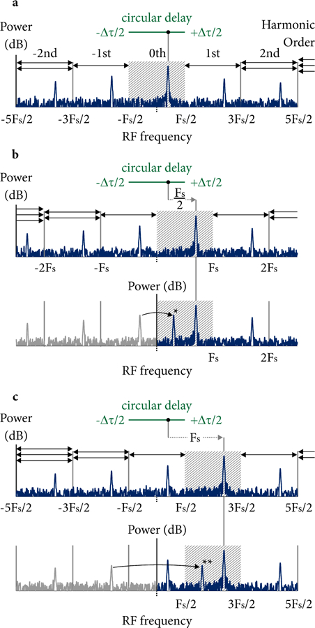
FIG. 6.

RF harmonic generation and resulting artifacts in time-stepped frequency comb circular ranging. (a) The RF content generated by a single reflection with denoted circular delay is shown for I/Q demodulation and without an AOFS. The signals are located in the baseband centered at DC, and RF harmonics of varying orders occur at higher positive and negative RF frequencies. The amplitude of the RF harmonics drops with order and is a function of the pulse shape. (b) Including an AOFS at Fs/2, while retaining I/Q outputs, shifts the baseband signals to the positive RF frequency space (upper panel). However, using a single channel (I only) causes the negative first order harmonic to appear within the base-band (lower panel denoted by *). (c) Increasing the AOFS frequency shift to Fs places the baseband further from DC, and shifts artifacts to the second negative order which have lower amplitudes.
