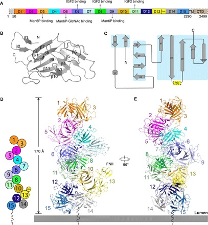
Fig. 1. Overall structure of the apo state of the IGF2R at pH 4.5.

(A) Schematic diagram of full-length IGF2R. Each domain is shown in different colors. The N terminus, transmembrane (TM) helix, and cytosolic domain (CTD) are not seen in the structure and are indicated with dashed boxes. (B) Secondary structure of a single domain. The secondary-structure elements are labeled. (C) Topology diagram for a single domain. All the secondary-structure elements are colored gray, and the β sheets are highlighted in the cyan boxes. The FNII domain of domain 13 is indicated by a yellow dashed box. (D) Diagram of the domain contacts in the apo state and overall structure of apo state IGF2R. The figure illustrates the interactions between the even-numbered domains and the odd-numbered domains at position X + 3. These interactions generate a helix-like shape (left). Domains in the same subgroup are indicated with dark and light colors. (E) Overall structure of apo state IGF2R rotated by 90°.
