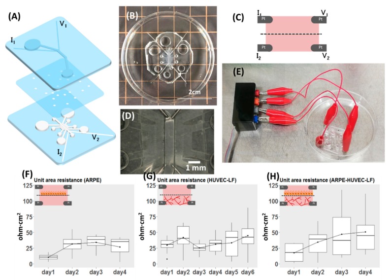
Figure 4.
Demonstration of the versatility of the proposed design, with modification for measuring TEER. (A) Exploded view of the device. (B) Top view of the assembled device. (C) Schematic view of the cross-section showing the position of voltage and current electrodes. (D) Magnified view of (B) focusing on the position of electrodes inside the device. (E) Part of the system set-up showing the connection of the device to the electrode adapter, which is connected to the EVOM instrument for TEER measurement. (F–H) Results of TEER measurement reported as unit area resistance. The inset for each plot shows what was measured of (F) TEER of ARPE monolayer (n = 4). (G) TEER of co-culture of HUVEC and NHLF (n = 10). (H) TEER of the oBRB model (n = 11).

