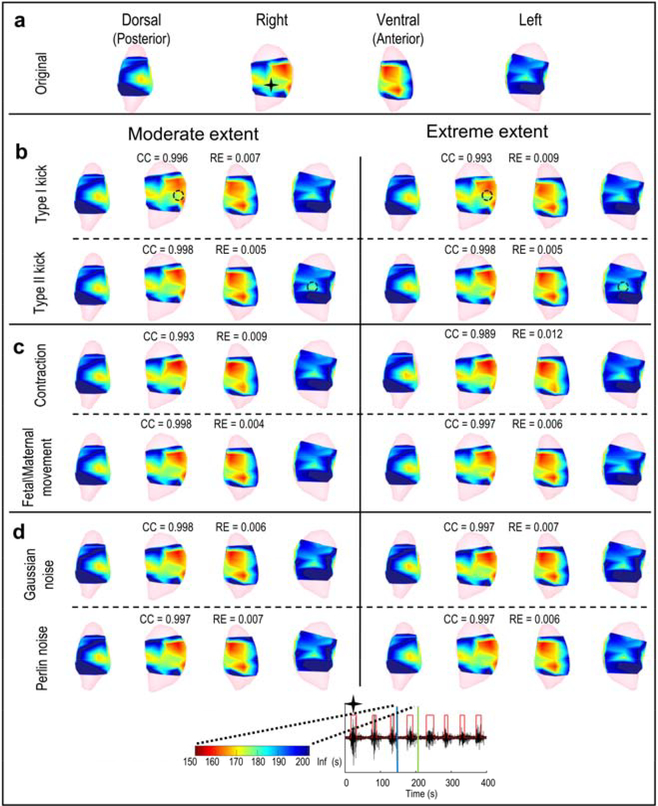
Figure 6. EMMI-reconstructed isochrone maps.
In the top seven rows, isochrones are displayed for extents of deformation or noise and shown in four views. In the heat maps, red indicates early activation, blue indicates late activation, and the darkest blue denotes regions in which no activation was recorded during the specific observation window. The black star indicates the location at which the electrogram (bottom row) was reconstructed. The electrogram shows EMG bursts (denoted by the red step lines); blue and green vertical lines indicate the start and end of the observation window for EMG burst (from 150 s to 201 s). a - d, Isochrones from original, local deformed, global deformed, and noise contaminated electrograms, respectively. Black circles in b mark local deformation centers.

