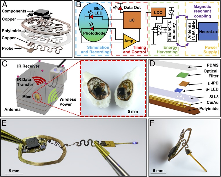
Fig. 1.
(A) Exploded-view schematic illustration of the photometry device. (B) Block diagram of the circuit function. (C) Rendered 3D schematic illustration of power delivery and data uplink for freely behaving mouse animal models. Inset shows implantation of both small (Right) and large (Left) devices on models of mouse skulls. (D) Schematic exploded-view illustration of a wireless, injectable photometry probe. (E) Photograph of a probe as it is powered in a configuration stretched from its original shape. (F) Side-view photograph of the device.

