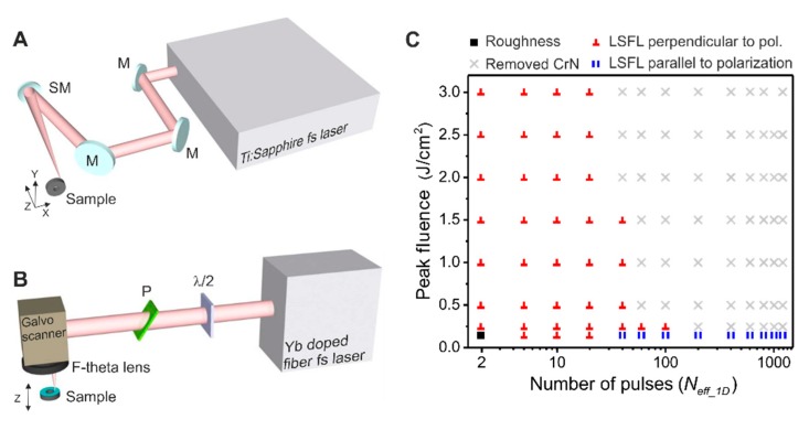
Figure 2.
(A) Setup of the Ti:Sa laser system (BAM). The beam is directed using several mirrors (M), the polarization is defined by a half-wave plate () and is finally focused in a static position on the sample by a spherical dielectric mirror (SM) of 500 mm focal length. The sample is positioned and translated by a motorized X-Y-Z translation stage. (B) Setup of the Yb-doped fiber laser (CSIC). The beam power is controlled by a combination of a half-wave plate () and a thin film polarizer (P). The beam scans the sample by a galvanometric mirror-based scanning head, and it is focused by a 100 mm F-theta lens. The sample is mounted in a Z-axis translation stage to control the focusing of the beam. (C) Plot that displays the obtained type of surface structures on CrN for a combination of number of effective pulses (Neff_1D) and peak fluences used for the formation of (■) roughness, (║) indicates the presence of , (⊥) indicates the presence of and (×) marks the conditions where the CrN layer has been destroyed.

