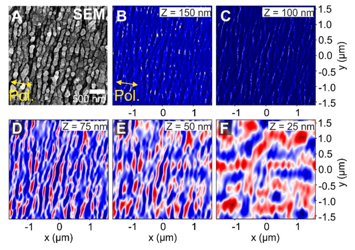
Figure 10.
FDTD simulation of a layered system that includes periodic HSFL = 100 nm given by the real structures shown in the SEM micrograph on the top left (A), HSFL modulation depth dHSFL = 75 nm, no added roughness (= 0 nm) and oxide layer thickness Tox = 100 nm. The intra oxide film position varies between Z = 150 nm (B), Z = 100 nm (C), Z = 75 nm (D), Z = 50 nm (E), and Z = 25 nm (F). The laser beam (λ = 800 nm) polarization direction is horizontal. The colors of the intensity plots are encoded in a false color scheme where red indicated deviations above and blue below the average intensity value of the image, represented in white.

