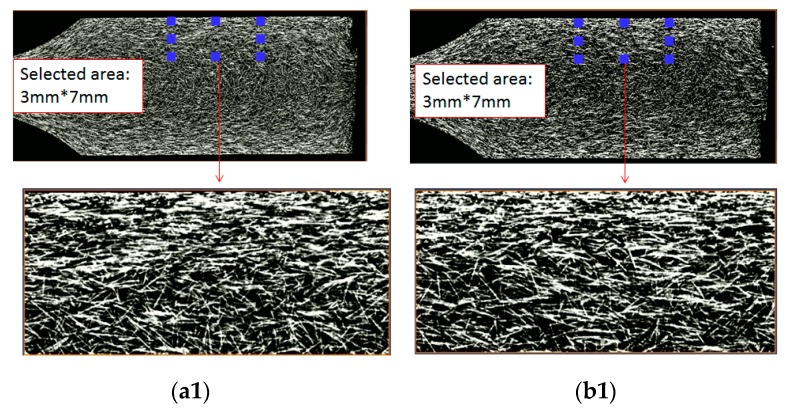
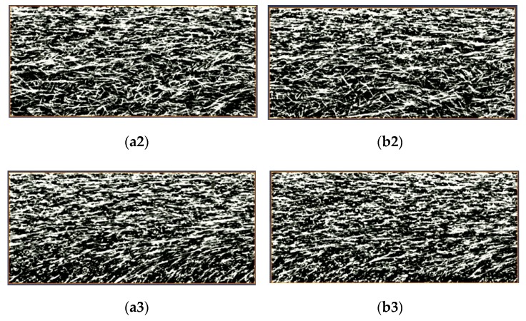
Figure 14.
Observation of the fiber morphology based on the sliced plane for the single-shot and co-injected parts at point A with different thickness locations: (a1) Single-shot at th = 0.5 mm, (b1) co-injected at th = 0.5 mm, (a2) single-shot at th = 1.0 mm, (b2) co-injected at th = 1.0 mm, (a3) single-shot at th = 1.75 mm (central portion), (b3) co-injected at th = 1.75 mm.


