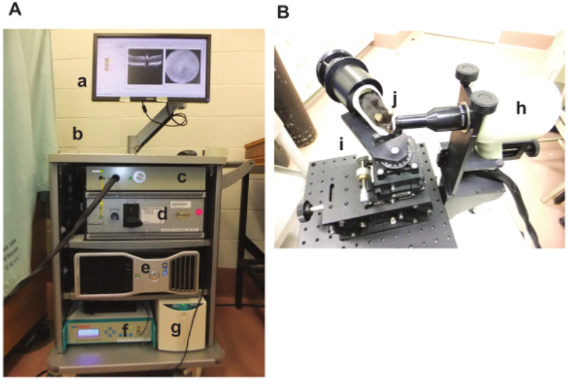
Figure 1: UHR-SD-OCT Device.
The HR-SD-OCT device used is shown. The instrument rack (A) contains the computer monitor (a), the keyboard and mouse (b), the probe interface box (c), the OCT engine (d), the computer (e), the control device for the super luminescent emitting diodes (infrared) (f), and the uninterruptible power supply (g). The optical bench (B) contains the imaging probe optical head (for mouse retina) (h), the multi-axis (linear and rotational) manipulator (i), and a mouse subject (j).

