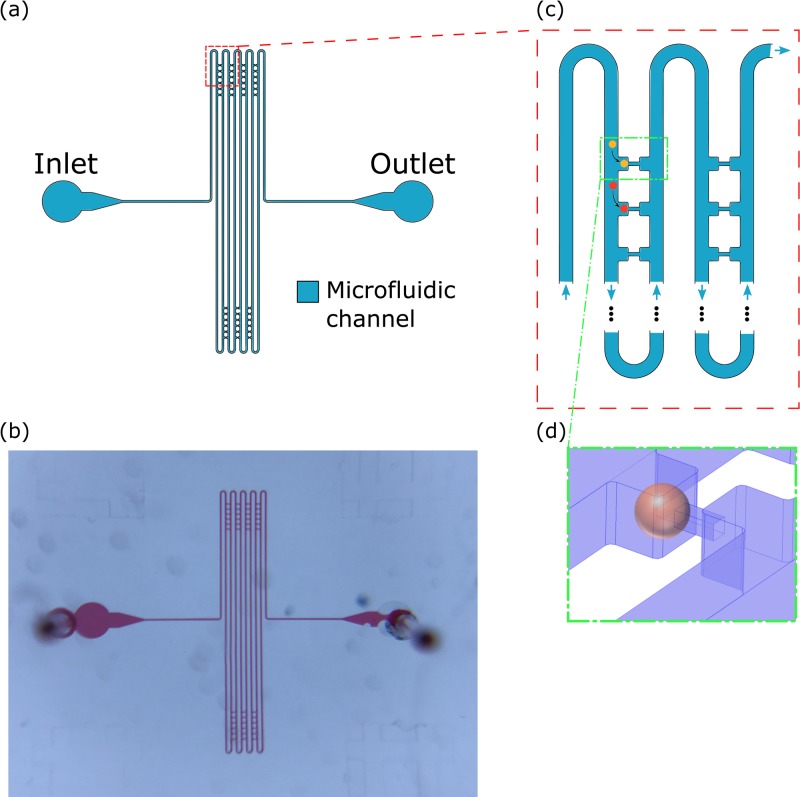
FIG. 2.
(a) Overall layout and (b) photo of microfluidic micropipette-aspiration (μFMA) device. (c) Zoomed-in schematic of the junction between micropipette-aspiration unit and main channel, where a cell would preferably enter the unit. (d) Zoomed-in schematic of a cell loaded at one micropipette-aspiration unit, where the pressure difference between the two ends is completely exerted on the loaded cell.

