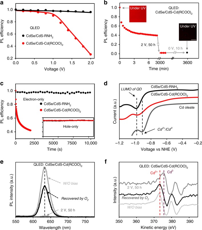
Fig. 2. Operando electrochemical reduction of the CdSe/CdS-Cd(RCOO)2 QDs.
a Relative PL efficiency of the QDs in the QLEDs as a function of the driving voltage. b Relative PL efficiency of the CdSe/CdS-Cd(RCOO)2 QDs in a QLED (driven at a constant voltage of 2 V for 50 h, followed by 0 V for 10 h). Insets are the corresponding photographs of the devices under ultraviolet irradiation (scale bar: 0.5 mm). c Relative PL efficiency of the QDs in electron-only devices (ITO/2,2’,2”-(1,3,5-Benzinetriyl)-tris(1-phenyl-1-H-benzimidazole) (TPBi, ~25 nm)/QDs (~40 nm)/Zn0.9Mg0.1O (~60 nm)/Ag, driven at a constant current density of 10 mA cm−2). Inset, the relative PL efficiency of the QDs in hole-only devices (ITO/PEDOT:PSS (~35 nm)/poly-TPD (~30 nm)/PVK (~5 nm)/QDs (~40 nm)/4,4′-Bis(N-carbazolyl)-1,1′-biphenyl (CBP, ~25 nm)/MoOx/Au) sharing the same coordinate axes with the main plot. The hole-only devices are driven at a constant current density of 30 mA cm−2 to ensure that only holes and no electrons are injected into the devices. d, The voltammetric curves of the two types of CdSe/CdS core/shell QDs and cadmium oleate. e and f, PL and differential auger electron spectra of the CdSe/CdS-Cd(RCOO)2 QDs in QLEDs under different conditions. The top electrodes are delaminated by adhesive tapes and the oxide electron-transporting layers are etched by a dilute acetonitrile solution of acetic acid, a known inert solution for the QD layer.

