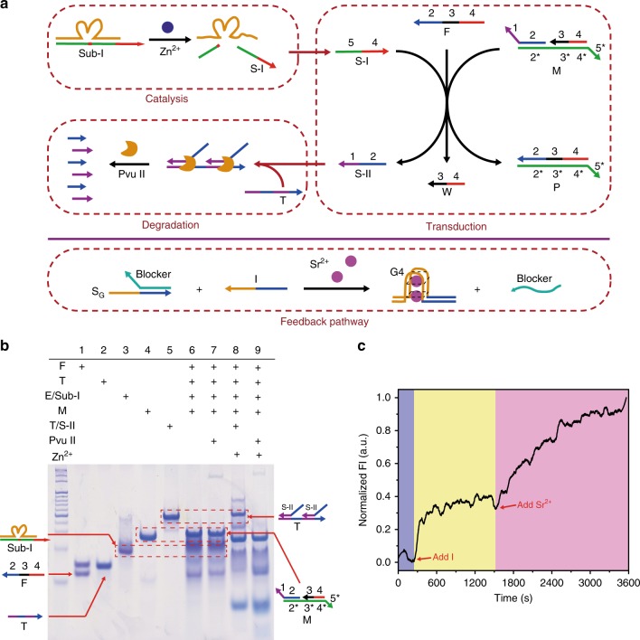
Fig. 4. Construction of an artificial molecular signaling network.
a Schematic representation of signaling network downstream modules and feedback module. Red dashed box indicates each confined reaction module. b Twelve percent PAGE analysis of signaling network modules, including ion-mediated catalytic reaction, a DNA circuit reaction and protein enzyme-assisted DNA degradation. DNA cascade reactions were performed in a 37 °C water bath. Lane 1: F strand; Lane 2: T strand; Lane 3: Hybrids of E and Sub-I (E/Sub-I); Lane 4: M strand; Lane 5: Hybrids of T and S-II (T/S-II); Lane 6: Former four DNA reagents; Lane 7: Sample in lane 6 treated with Pvu II; Lane 8: Samples of lane 6 adding zinc ion; Lane 9: Samples of lane 6 treated with Pvu II and zinc ion. Plus (“+”) mark indicates the presence of the corresponding molecule. c Fluorescence kinetics showing the dynamic DNA strand displacement of feedback pathway. As shown by the red arrow, the 20 nM strand I and 10 mM Sr2+ were successively added into the 20 nM SGR duplex solution. Source data are provided in the Source Data file.

