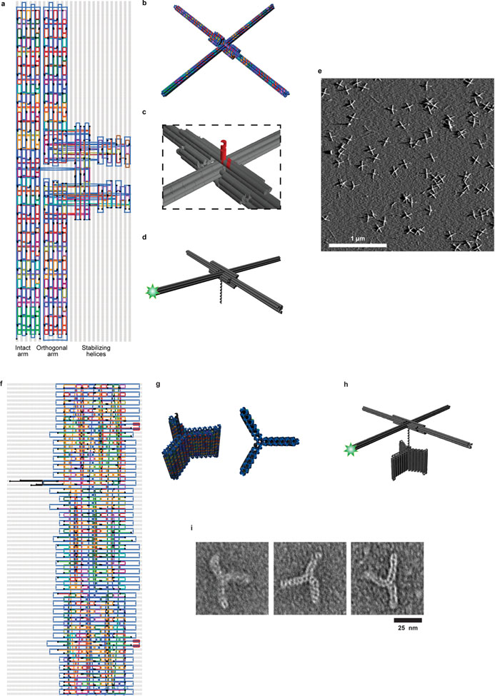
Extended Data Figure 1 |. Origami rotor and anchor designs.
a, Routing diagram of the origami rotor consisting of two 160-nm arms (Supplementary Table 1). The intact arm (a six-helix bundle) passes through a break in the orthogonal arm (two half-length six-helix bundles). Additional helices stabilize the junction. Two of these helices contain staple strands (black) that are extended from the center of rotor (extension not shown; see (c)). Six staples within 14 nm of the end of the intact arm (light green) are labeled with Cy3 at their 3’ ends. b, 3D rendering of the rotor design. c, Magnified view showing the two staple strands (red) extending from the center of the rotor, forming a 14-bp dsDNA and a 12-nt ssDNA overhang for ligation. d, The overhang is ligated to a longer piece of dsDNA, which serves as the substrate of the DNA-interacting enzyme. e, A large field of view AFM image of origami rotors, representative of more than 10 independent biological replicates. Scale bar: 1 μm. f, Routing diagram of the origami anchor consisting of three 20-nm wing, each made of a short six-helix bundle motif (Supplementary Table 2). Several staple strands were extended with binding sites for biotin-labeled secondary oligomers for surface attachment. From the center of the structure, three strands (black) were used to make an adaptor to allow ligation to additional DNA. Following the final strand crossover, the adaptor consists of 26 bp of dsDNA followed by a 12-nt ssDNA overhang. g, 3D renderings of the origami anchor. h, Origami structure used for characterizing the Brownian dynamics. The origami rotor, anchor, and a dsDNA linker (as needed), were ligated together. The origami anchor is attached to the microscope surface using multiple biotin tags. i, Representative images of the origami anchors from one TEM experiment.

