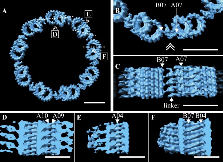
Figure 6.
Defining features of the TZ. (A) The TZ average was used to regenerate the idealized symmetry of the TZ, where adjacent DMTs were connected via the TZ-linker. (B) A zoom-in view of two adjacent DMT shows how the TZ-linker spans adjacent DMTs, with the major contacts between A07 and B07, with B06 also contributing. (C) When viewed from the side (double arrowhead in B denotes viewing perspective in C), the 8-nm periodicity of the TZ-linker was apparent. (D and E) Shelf-shaped MIPs within the A-tubule formed a discontinuous helix that followed the internal lattice of the microtubule. The MIP helix was broken at the microtubule seam between protofilaments A09/A10 (D) and at protofilament A04 (E). (F) Within the B-tubule, similar shelf-shaped MIPs also straddled several protofilaments, from B04 to B07. Insets in A show the slice (dashed line) through the average and the viewing angle (double arrowhead) for D–F. Scale bars are 50 nm (A–C); 25 nm (D–F).

