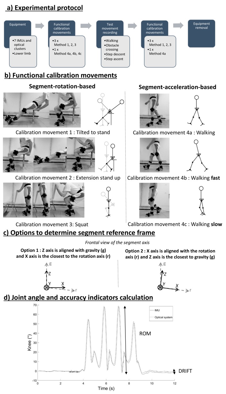
Figure 2.
(a) Experimental protocol. (b) Functional calibration movements: for movements 1, 2, and 3, where the second axis was defined as the principal rotational axis as determined by a principal component analysis (PCA) on gyroscope signals; for movements 4a, 4b, and 4c, the second axis was defined as the principal acceleration axis through a PCA on accelerometer signals. (c) Two options to determine the segment reference frames, as shown in segment frontal views. (d) The accuracy was assessed using the root mean square error (RMSE), the absolute difference in the range of motion (ΔROM) between both systems, and the absolute drift accumulated during the movement (DRIFT).

