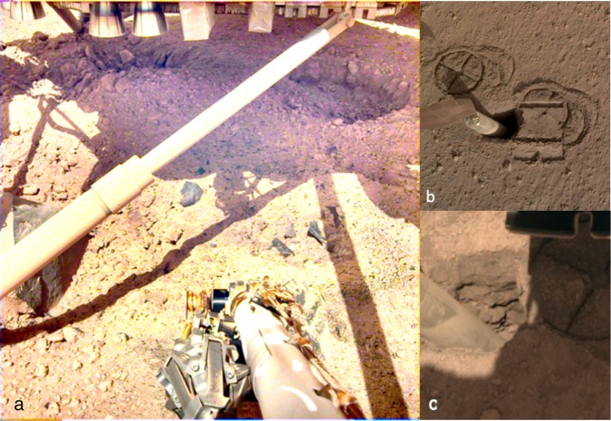
Fig. 8. Images of shallow subsurface structure.
a Image shows pits under the lander with spacecraft strut, retrorockets, excavated pits (~10 cm deep, ~50 cm across), dark gray, very fine-grained rocks (basalt) and duricrust. Note steep pit walls of soil and clasts in a finer-grained matrix, indicating cemented duricrust and clods and fragments of the duricrust that litter the pits and surface. Pulsed retrorockets on the Phoenix lander eroded 5–18 cm of material beneath the lander42. A contrast stretch has been applied to this image to accentuate details in the shadowed areas. b Image of mole hole and surface after interactions with the HP3 SSA feet and scoop. Circular cross patterns are imprints of the HP3 SSA feet in the soil. Smooth, reflective rectangular surface is where the flat base of the scoop (7.1 cm wide) was pressed against the soil, causing a ~5 mm indentation. Note the horseshoe shaped outline of the front blade of the scoop imprint (Fig. 7a). Horizontal troughs near the top and bottom of the scoop imprint are where the front blade of the scoop penetrated into the soil. c) Image of hole created by the HP3 mole showing resistant layers in the wall of the pit. These layers have steep edges and overhangs indicating cohesion in the soil. Small rocks appear cemented in a fine-grained matrix, similar to the pits beneath the lander. Mole is angled 2.7 cm diameter cylinder (~15°), to the left.

