
Fig. 1.
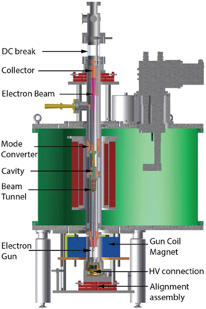
The schematic of the 527 GHz gyrotron in a 10 T SCM (shown in green) is shown. Different components of the tube assembly are labeled. The gyrotron tube is mounted on two assemblies at the top and bottom for alignment along the magnetic field axis.