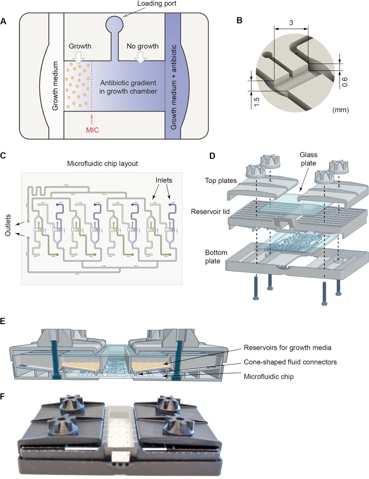
FIG 1.
Overview of the fluidic system. (A) Illustration showing a growth chamber and a loading port used to inject the bacterium-agarose mix. The growth chamber is flanked by two flow channels. Antibiotic gradients in the growth chamber are created by diffusion from the source channel (blue) containing growth medium as well as a high concentration of the antibiotic to the sink channel (white) containing only growth medium. Bacteria present in the growth chamber are exposed to the diffusion-limited antibiotic gradient, and the MIC value will correspond to the lowest concentration at which the bacteria do not grow to form microcolonies (shown in this example as a red dashed line). (B) A close-up view of a growth chamber with the dimensions indicated. (C) Overview of the microfluidic chip holding eight growth chambers. The fluidic outlets that are connected to a pump are indicated, as well as the inlets (16 in total) that are connected to the reservoir lid. (D) Drawing showing how the bottom plate, fluidic chip, reservoir lid, and top plates are assembled. (E) Cartoon showing the assembled system from the side highlighting the connections between the reservoir lid and the fluidic chip via fluid connectors. (F) Photograph of the assembled system.

