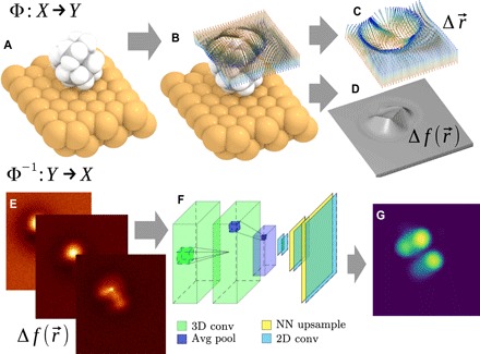
Fig. 1. Schematic illustration of the CO-tip AFM imaging process and the proposed solution for the inverse imaging problem.

(A to D) The imaging process Φ : X→ Y of molecular geometry X (A) originates predominantly from probe particle (PP) displacement due to interactions with sample atoms (B). The resulting PP displacement is plotted in (C). The fibers show deflection of the PP as it approaches the surface, with the red-blue gradient representing the tip-sample distance (red, far; blue, close). (D) The resulting AFM frequency shift [] images Y obtained by integrating the forces felt by the relaxed PP over its path. (E to G) The inverse imaging process (i.e., reconstruction of geometry) Φ−1 : Y→ X approximated by a convolutional NN (F) transforming a 3D stack of AFM images Y (E) to a description of the molecular geometry X [represented by, e.g., van der Waals spheres (G)].
