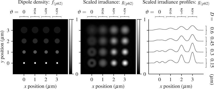
Fig. 6.

Left: A spatially dense and angularly sparse phantom—uniformly spaced disks with varying size (increasing D from bottom to top) and dipole orientation (increasing ϑ from left to right) Center: Scaled irradiance for an imaging system with NA = 0.75, λ = 500 nm, and no = 1.33 sampled at 20× the Nyquist rate. Right: x profiles through the scaled irradiance. Larger disks generate increasingly uniform irradiance patterns with fewer details that may indicate the orientation of fluorophores.
