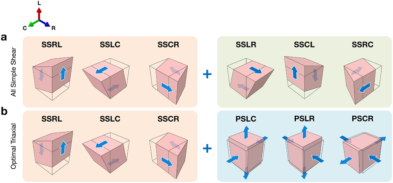
Figure 2:
Diagrams of loading paths applied to a cuboidal myocardium specimen with edges aligned to the anatomical directions of the heart (see Figure 3a), with the undeformed geometry shown by the black outline. (a) The “All Simple Shear” loading paths emulating the experiments performed by Dokos et al. [13]. (b) “Optimal Triaxial” loading paths that minimize the covariance in parameter estimation. Note that the first three simple shear paths (orange) are common to both sets; in the “Optimal Triaxial” set, fewer simple shear paths are included compared to “All Simple Shear,” (green), and pure shear deformations are introduced (blue). Abbreviations: longitudinal (L), circumferential (C), radial (R).

