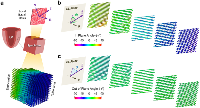
Figure 4:
(a) Schematic of a tissue specimen with a representative laminar sheet isolated, showing the local fiber-sheet-normal basis, and representative fiber directions from processed DTI, with fiber angle ϕ computed with respect to the circumferential direction. (b–c) Selected circumferential-longitudinal planes along the radial direction showing the (b) in plane angle ϕ and (c) out of plane angle θ of the fiber direction. Abbreviations: fiber (f), sheet (s), normal (n), circumferential-longitudinal (CL). All DTI was visualized using ParaView [42].

