
Figure 1:
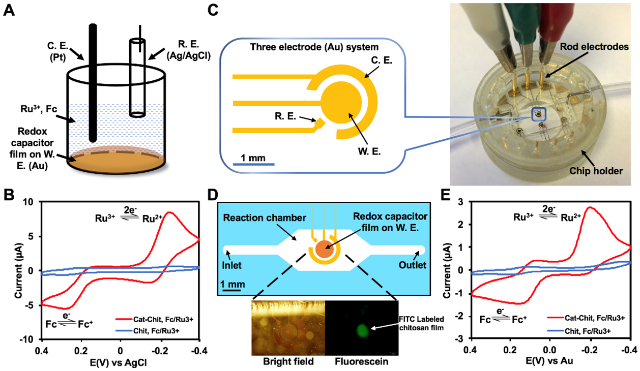
(A) Setup of a standard three-electrode electrochemical cell. The BBRC film is deposited on the working electrode. The system is characterized in a solution of Ru3+ and Fc. (B) Cyclic voltammogram (CV) comparing standard gold electrode modified with BBRC film (Cat-Chit) and chitosan film (Chit) using chamber in (A). (C) A miniaturized three-electrode electrochemical system designed and built inside a microdevice that is enclosed in a 3D printed chip holder. (D) Schematics showing the configuration of the molectronic sensor. The three-electrode system is contained within a reaction chamber. Lower panels depict bright field (BF) and fluorescent microscopic images of the functionalized electronics. (E) CV comparing the molectronic biosensor (Cat-Chit) and the control device (Chit) using electrode system in (D). W. E.: working electrode, C. E.: counter electrode, R. E.: reference electrode.