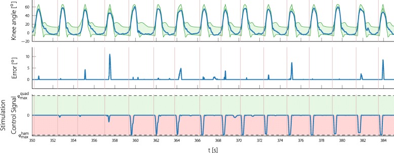
Fig. 13.
Continuous time experiment data of the knee ILC. The knee angle and the stimulation signal are shown as seen during the experiment. The reference bands and the error signal are plotted in an acausal way, since the assessment for each cycle is done at the end of the cycle. The shown data is part of the experiment with participant 2. Note that the positive plane of the stimulation control signal was normalized to the maximum quadriceps stimulation intensity (8.57µAs) and the negative plane to the maximum hamstrings stimulation intensity (14.36µAs). Due to the cocontraction mapping strategy, a stimulation control signal of zero still leads to a certain stimulation. The vertical lines ( ) mark the heel-off events

