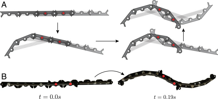
Fig. 7.
Inflection point. (A) A profile with an inflection point can be obtained by connecting two linkages with next-nearest connections. The joints at which the two linkages are connected together are shown with red circles. (B) Experimental snapshot of a structure in the initial and final configurations. Each linkage consists of four bars with and .

