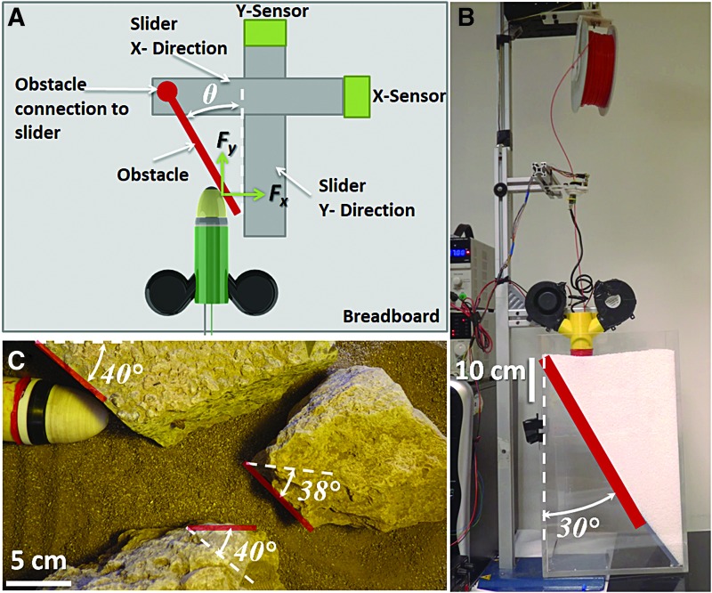
FIG. 2.
(A) Schematic view of the load cells and sliders connection with the obstacle. (B) Setup to test the robotic root in an artificial soil (polyoxymethylene granules, with a diameter of 4 mm) with an obstacle at 30°. The container had an inside dimension of 28 × 28 × 42 cm W × L × H, up to the soil surface, and the obstacle was placed diagonally. (C) Real unstructured environment reconstruction with rocks at different angles and sandy terrain. In (C), the barrier angles have been evaluated considering tip direction at the instant of incidence (white dashed lines). (A) Used to characterize body structural material behavior when facing an obstacle, purposely using a smooth surface. (B, C) Additional tests to verify the feasibility of our system to move in more articulated environments. Color images are available online.

