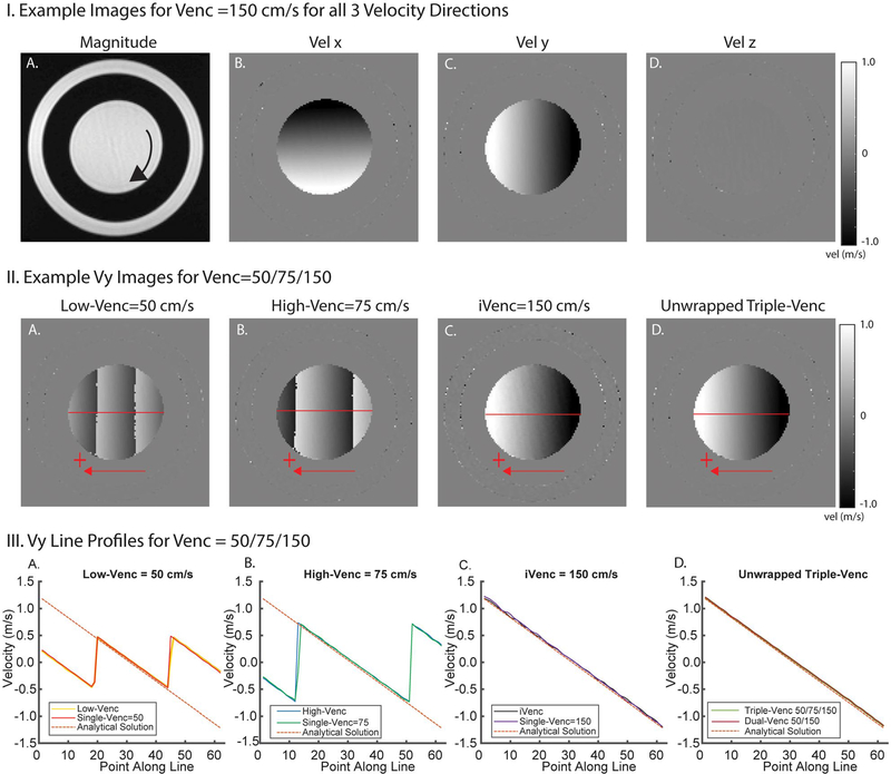
FIGURE 2.
Example rotation phantom images and results. I, Example images for all 3 velocity directions (Vx, Vy, Vz) showing velocity gradients in in-plane velocity encoding directions (x, y). II, Example Vx images from a triple-VENC acquisition. Low-VENC and high-VENC images show different degrees of velocity aliasing. The unwrapped image has the benefit of decreased velocity noise from the low-VENC image and no velocity aliasing. This reduced noise can be seen in comparing the triple-VENC and iVENC images (IIC,D). III, Velocity profiles along a horizontal line (illustrated in red) in the Vx images, showing the velocity values in reconstructed low-VENC, high-VENC, and iVENC phase difference images compared with their corresponding single-VENC acquisitions. Unwrapped triple-VENC velocity profiles are also in agreement with those of the corresponding dual-VENC acquisition

