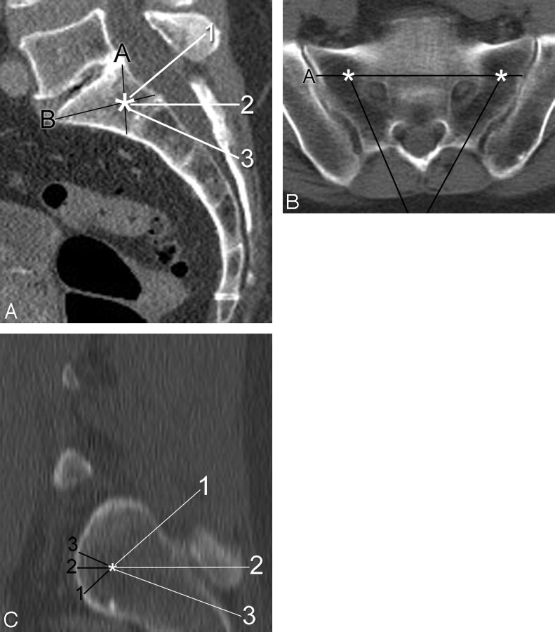
Fig 1.
Demonstration of measurements made during virtual needle placement on a CT scan of the pelvis in a 65-year-old woman. A, On a sagittal midline reconstructed image, note the target (asterisk) by the intersection of line A (from the posterosuperior corner of S1 to the anteroinferior corner of S1) with line B (from the anterosuperior corner of S1 to the posteroinferior corner of S1). Three possible needle trajectories have been described and are indicated by the numbered white lines: 1) parallel to the L5-S1 disk space, 2) neutral or axial with respect to the patient, and 3) along the sacral long axis. B, Axial image taken along line 2 (axial plane) from the same patient demonstrates the target zones (asterisks) for each sacral ala. Line A represents the projection of line A from the sagittal image (A). Note how the 2 needle trajectories (black lines) are both parallel to their respective sacroiliac joints. C, Sagittal oblique image obtained along a line parallel to the sacroiliac joint shows the relative location of the target (asterisk) within the lateral sacrum. The distance from the target point to the anterior sacral cortex was obtained for the 3 needle trajectories described previously.

