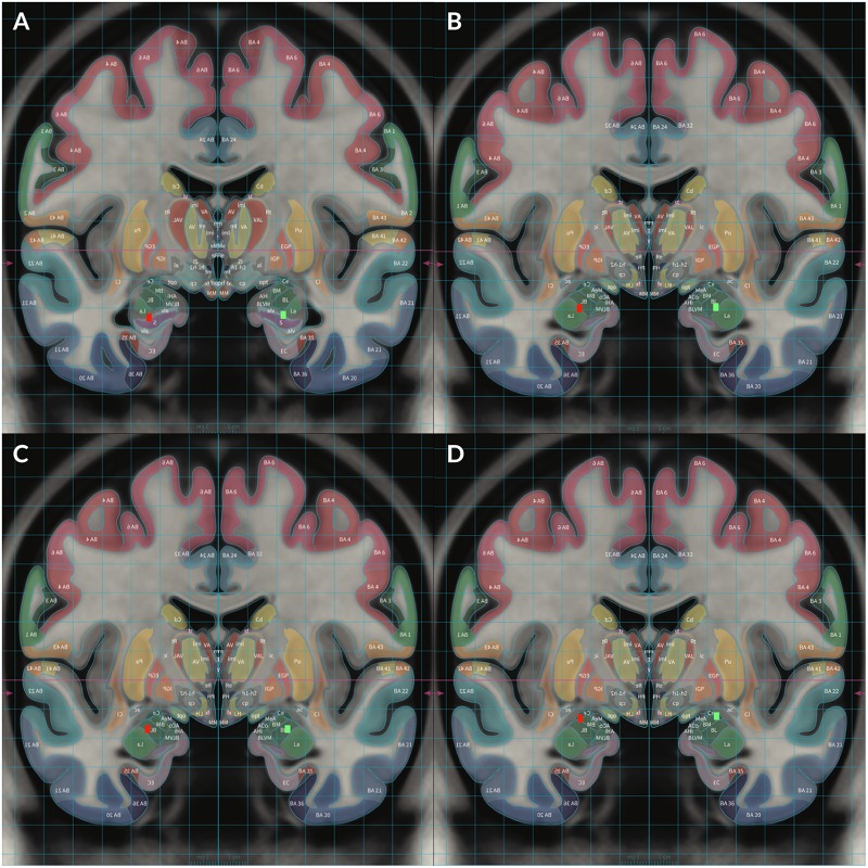
FIGURE 2.
To demonstrate locations of each electrode, Subject 2’s MRI brain imaging studies were registered to the MNI space (MNI152 NLIN2009a) and then overlaid on the structural atlas of Mai (Horn and Kühn, 2015; Mai and Majtanik, 2017) to allow delineation of cerebral cortices and subcortical structures with color coded representations of cortical and subcortical parcelation according to the Mai atlas. The red rectangular markers represent right sided DBS electrode contacts 8–11 while the green rectangular markers represent left sided contacts 0–3. Contact 0 was placed in the left HC and contact 8 was placed in the right HC (A). Contact 1 was placed in the left ventral BLA and contact 9 was placed in the right ventral BLA (B). Contact 2 was placed in the left dorsal BLA and contact 10 was placed in the right dorsal BLA (C). Contact 3 was placed in the left CeA and contact 11 was placed in the right CeA (D).

