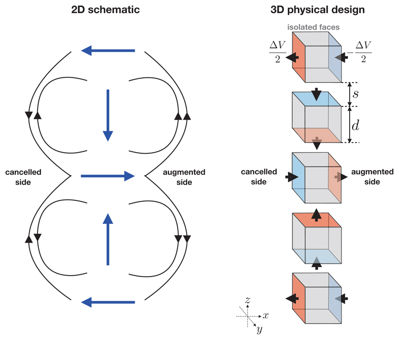
Figure 3.
Left: a two-dimensional schematic of the electric field (black arrows) produced by a Halbach bipole array showing the bipole vectors (blue arrows, pointing from positive to negative). Locally, the field directions point in the same direction on the right-hand-side of the bipole array and point in the opposite direction on the left-hand-side of the bipole array. Right: A three-dimensional design of a simple Halbach electrode configuration consisting of five cubic electrode “elements” arranged in a column, parameterized by the electrode edge length d and spacing s. A potential difference of ΔV is applied between charged faces (shown with red and blue colours). Gray faces are not charged and are electrically isolated from the rest of the circuit. The black arrows show the direction of the electric current. The particular arrangement shown augments the electric field in the +x direction, and cancels it in the −x direction. The augmented and cancelled directions may be swapped either by swapping the polarities of the 2nd and 4th elements, or the 1st, 3rd and 5th elements.

