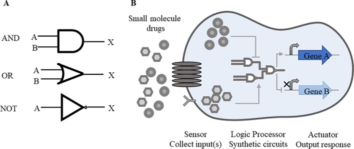
Figure 1.
Basic synthetic circuits working pattern. (A) Common logic gates. “AND”, “OR” and “NOT” logic gates are commonly used forms in synthetic circuits. A, B represent inputs and X represents output. Simple symbols are used to express the logical relations between inputs and outputs. In “AND” gate, both inputs A and B are required for the output of X. In “OR” gate, either A or B is required for the output. In “NOT” gate, once the input A is working, the output X is suppressed. These logic gates function alone or in combination according to the level of regulation. (B) Drug-responsive synthetic circuits. In drug-responsive synthetic circuits, drugs often perform as inputs to initiate whole circuits. When drugs enter inside cells by going cross cell membrane or combining with receptors on the surface of membrane, logic gates response to drugs, following the transcription of target genes and other essential genes will be activated or repressed consequently.

