-
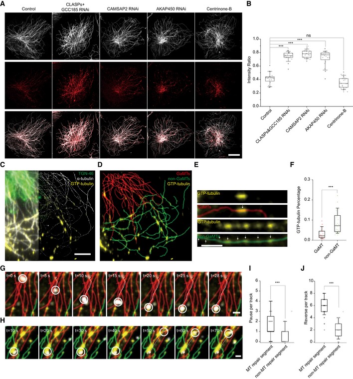
A
Five representative images of MT repair sites in HRPE cells under combinative KDs. Cells were rotated to orient their leading edges locating in the 1st quadrant. From left to right, control cell, CLASPs&GCC185 KD cell, CAMSAP2 KD cell, AKAP450 KD cell, and centrinone‐B‐treated cell. Gray: α‐tubulin; red: GTP‐tubulin. Scale bar: 20 μm.
-
B
Box–whisker plot presents intensity analysis of MT repair sites in HRPE cells under combinative KDs (one representative of three independent experiments and n = 20 cells). ***P < 0.001, unpaired t‐test.
-
C
Conventional image (left) and STORM image (right) of MTs and MT repair sites. Gray: α‐tubulin; yellow: GTP‐tubulin; green: Golgi. Scale bar: 5 μm.
-
D
MT repair sites on GaMTs and non‐GaMTs extracted from (C). Red: GaMTs; green: non‐GaMTs; yellow: GTP‐tubulin.
-
E
MT repair sites on GaMTs and non‐GaMTs separately presented in detail. White arrows indicate GTP‐tubulin‐labeling sites. Scale bar: 5 μm.
-
F
Box–whisker plot presents the ratio of MT repair sites on GaMTs and non‐GaMTs separately (one representative of three independent experiments and n = 8 cells). ***P < 0.001, unpaired t‐test.
-
G
Representative time series show one fast cargo moving on a GaMT and slowing down at the MT repair site. Red: GaMT; green: non‐GaMT; yellow: GTP‐tubulin; white circle: cargo position. Scale bar: 2 μm.
-
H
Representative time series show one cargo moving fast between two MT repair sites and slowing down at the MT repair sites. Red: GaMT; green: non‐GaMT; yellow: GTP‐tubulin; white circle: cargo position. Scale bar: 2 μm.
-
L, J
Pause (I) and reverse (J) events of cargos on MT repair segment and non‐MTs repair segment, respectively (data were pooled from two independent experiments and n = 22 cells). ***P < 0.001, ns, no significant difference, unpaired t‐test.
Data information: The ends of the whiskers are set at 10 and 90% of the entire population.