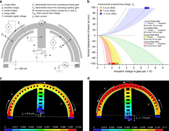
Fig. 2. Forces and rotation moments in relay with serpentine hinge.
a Relay with a positive hinge offset L1, defined as the vertical displacement of the hinge anchor point from the geometric centre of the circular beam. A negative hinge offset would result in the hinge anchor point being situated below the centre. When a voltage V is applied simultaneously on the principal and auxiliary gate pair 1, the resultant electrostatic fields across the two respective airgaps produce radially directed forces as shown. These forces resolve to realise a net clockwise rotational moment for positive hinge offsets, and an anticlockwise rotational moment for negative hinge offsets. b Measured programming voltages (circles) for different hinge offsets where the beam tip moves down 100 nm vertically to make contact with the drain. Multiple devices with the same hinge offset were tested with the differences in programming voltage due to fabrication non-uniformities across the die. Also shown are the predictions from the analytical model (dashed lines, model described in Supplementary Note 1 and Supplementary Fig. 1) and Ansys finite-element model (bands) for a range of hinge widths. Other than the hinge offsets, the geometry of the devices are identical and shown in Supplementary Table 1. c, d Ansys simulation of the total displacement for different hinge offsets of otherwise identical devices where the device is actuated in both instances by driving principal and auxiliary gate pair 1. The colour bar represents vertical displacement with red corresponding to 100 nm, the drain-to-beam-tip airgap.

