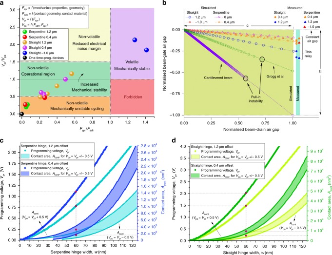
Fig. 3. Regimes of operation and scaling study.
a Operating regimes of NEM relays for serpentine and straight hinges. The condition Fadh = Fspr separates the regions where the device is volatile or non-volatile, while Vpr = Vpo separates the regions where the applied reprogramming voltage causes the device to be overdriven or not. The plot is populated with data points measured in ambient air, room temperature experiments showing NEM relays operating in each regime. b Comparison with prior art of uniformity of beam-to-gate airgap g vs. beam-to-drain airgap c as the relay moves, based on finite-element simulations. The beam-to-gate airgap of the moment-driven relay has under 6% variation for small and negative hinge offsets for the entire range of operation. In contrast, the beam-to-gate airgap decreases by nearly 100% at the beam tip in straight cantilever, bridge, see-saw and crab leg relay architectures unless restricted by the contact dimple. The curved beam relay reported by Grogg et al.11 experiences a ~50% reduction in the airgap at contact. The simulation plot also shows the proposed NEM relay does not exhibit pull-in instability. The measured beam-to-gate displacements after actuation were obtained from SEM scans of the device after beam rotation. This experimental data is plotted on the right. c, d Scaling study showing variation of programming voltage (i.e. voltage required for closure from a neutral state) with hinge width for actuation and contact airgaps of 60 nm, and contact area needed to achieve a reprogramming voltage within 0.5 V of the programming voltage.

