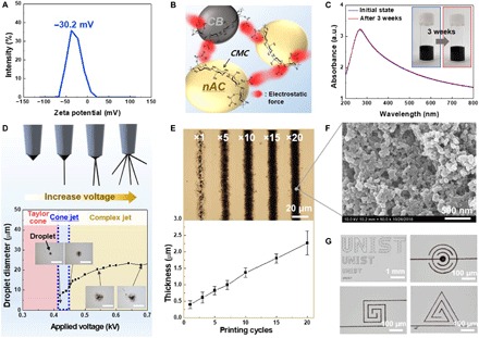
Fig. 2. Design of electrode inks and fabrication of electrodes via EHD jet printing.

(A) Zeta potential profile of the electrode ink containing the CMC binder that acts as a surface charge–tuning agent of the nAC particles. (B) Schematic of the electrode ink representing the CMC-assisted electrostatic repulsion and its beneficial effect on the dispersion stability. (C) UV-vis absorption spectra and photographs (inset) of the electrode inks (initially and after 3 weeks). a.u., arbitrary units. (D) Conceptual depiction of various EHD jetting modes and change in the diameter of the ejected electrode droplets as a function of applied voltage. Insets are photographs of the droplets in different jetting modes. Scale bars, 20 μm. (E) Optical microscopy images and thickness variation of the electrodes as a function of printing cycles. (F) SEM image of the printed electrode (20 printing cycles). (G) Photographs of letter (“UNIST”)-shaped printed electrodes of different sizes and micrometer-sized printed electrodes with various form factors. Photo credit: (C) Kwon-Hyung Lee, Ulsan National Institute of Science and Technology.
