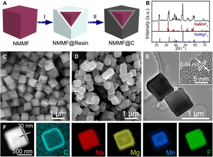
Fig. 2. Fabrication strategy and characterizations of the NMMF@C microcubes.

(A) Synthetic scheme of the NMMF@C cubes, which includes two steps: I, coating resorcinol-formaldehyde resin on the as-prepared cubes; II, carbonization at high temperature. (B) XRD pattern of the NMMF@C cubes together with two standard patterns. a.u., arbitrary units. (C) FESEM image of the NMMF cubes. (D) FESEM image of NMMF@C cubes. (E) TEM images of the NMMF@C cubes. Inset is a HRTEM image taken from the region indicated by a white square. (F) STEM and elemental mapping images of the Na, Mg, C, Mn, and F elements of a single NMMF@C cube.
