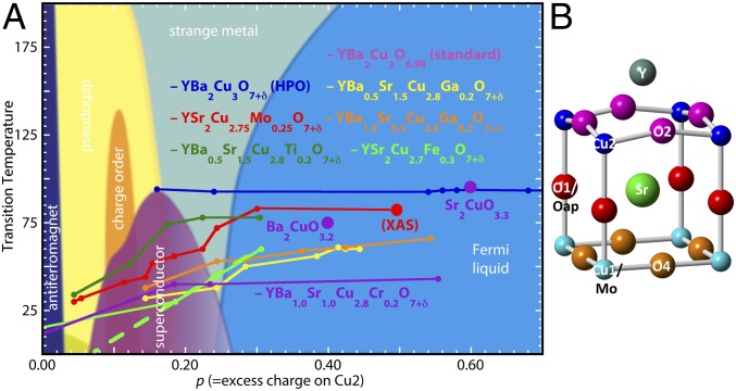
Fig. 1.
(A) Conventional phase diagram for YBCO with the addition of YSCO-Mo and other HPO compounds whose superconducting regions (9, 10, 13, 27, 70, 71) do not conform to the “dome” found for materials prepared by oxidation with O2. (B) Half of the unit cell from the crystallographic structure (13) of YSCO-Mo, with labels as in SI Appendix, Fig. S1. The c axis is across the figure, through the Cu2–O1–Cu1 axis, with the CuO2 plane adjacent to the Y and the Cu of the chains on the right side going vertically on and out of the page. One-fourth of the Cu1 are replaced by Mo. Cu1 and the substituting Mo are in the chains, Cu2 is in the CuO2 planes, O1 or Oap is the apical O bridging Cu1/Mo with Cu2, O2 bridges between the Cu2 sites in the CuO2 planes (this is also O3 in orthorhombic YBCO because YSCO-Mo is tetragonal), O4 bridges the Cu1/Mo sites, and the XAFS results do not require the O5 or O6 sites of the YSCO-Mo crystal structure (SI Appendix, Fig. S1). Although the crystal structure places the O5 and O6 atoms of the Cu–Mo layer off of the Cu–Cu axes as in the crystal structure, the Cu–O and Mo–O distances determined by the XAFS locate the O4 atoms directly between the Mo–Mo and Cu–Cu pairs.

