
Extended Figure 9.
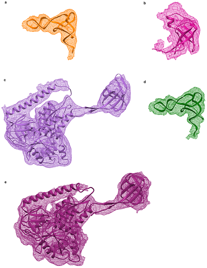
Views of the major components of the 30S IC and 70S IC after structural modeling of the 30S IC and 70S IC using the MDFF method. (a) fMet-tRNAfMet (orange) in its 30S P/I configuration in the 30S IC. (b) IF1 (magenta) in the 30S IC. (c) IF2 (light purple) in the 30S IC. (d) fMet-tRNAfMet (green) in its 70S P/I configuration in the 70S IC. (e) IF2 (dark purple) in the 70S IC. For each component, the reconstructed Coulomb potential is represented by the mesh and the structural model is represented by secondary structure cartoons.