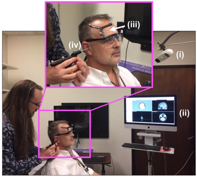
Figure 2.

Neuro-navigation setup. To define a coordinate system for subsequent placement of the TMS and DU devices, the (i) infrared navigation system facilitated projection of (ii) a standard head model onto the participant’s head (PDM here), identified grossly by (iii) an infrared-reflective marker placed at a predetermined position on the participant’s head then in a more refined way through placement (by JA here) of the tip of a (iv) pointing device (the “phaser”), with infrared reflective markers on each ear as shown, and the bridge of the nose.
