
Figure 1.
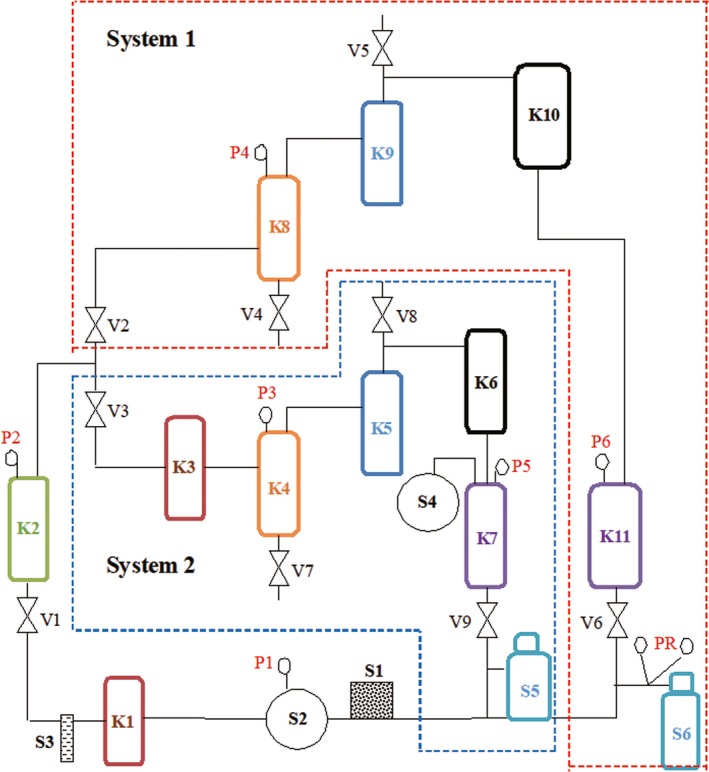
Schematic diagram of continuous phase‐transition extraction system. S1: microfilter; S2: high pressure pump; S3: flowmeter; S4: vacuum pump; S5 and S6: ethanol; Vi (i = 1, 2, 3 to 9): valve; Pi (i = 1, 2, 3 to 6): pressure indicator; K1 and K3: heat exchanger; K2: extraction pot; K4 and K8: separation pot; K5 and K9: purification column; K6 and K10: condenser; K7 and K11: solvent storage pot