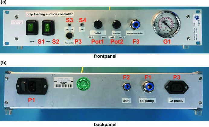
Figure 6.
The vacuum control unit. (a) View of the front panel. From left to right: mains switches for the control unit (S1) and the pump (S2), a connector for the foot paddle (P3), control switches for the vacuum (S3), and filter insertion to control the vacuum ramp up/down (S4). Vacuum level (Pot1) and filter insertion rate (Pot2) can be adjusted using analogue potentiometers. An outlet port with push-in fitting (F3) connects the vacuum pump to the chip-loading block and an analogue pressure gauge (G1) aids in setting the desired backpressure. (b) View of the back panel. From left to right: 230 V power socket (P1), vent to atmosphere (F2), inlet port with push-in fitting connecting to the vacuum pump (F1) and membrane pump power feed-through (P2).

