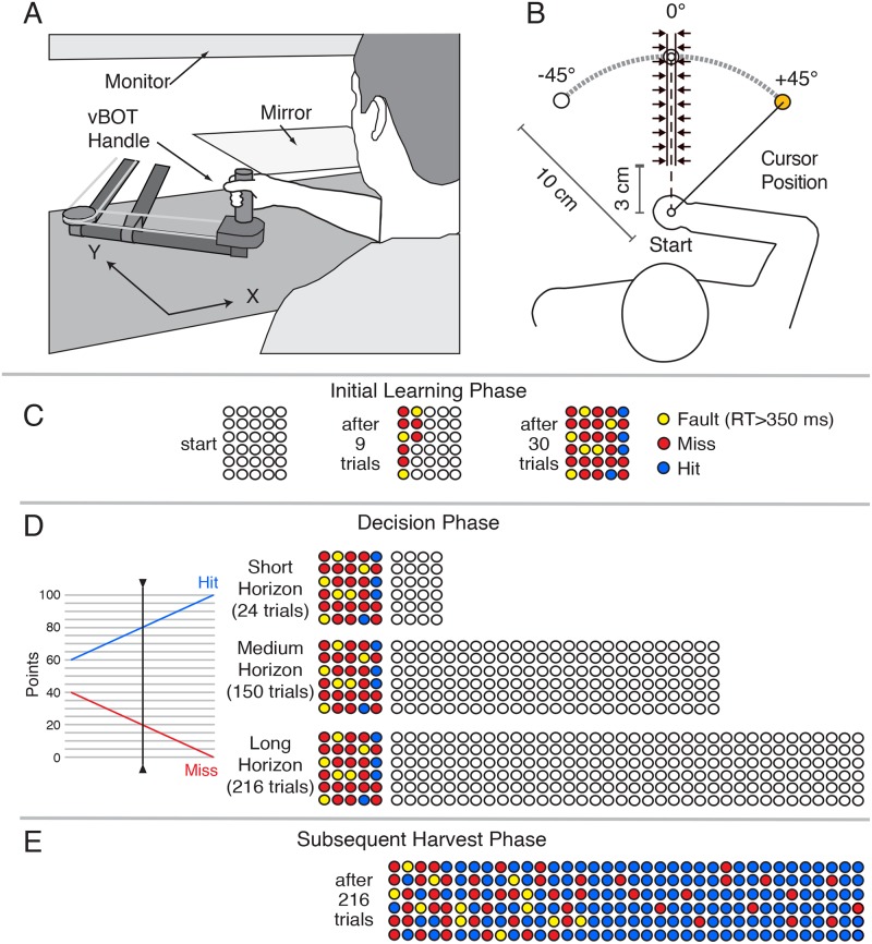
Fig 7.
(A) Schematic of robotic device and virtual reality setup used in Experiment 2. (B) Top view showing the locations of the start location and three targets. A force channel, represented by the arrows, constrained the movement to a straight line path in the direction of initial movement. During visuomotor rotation trials, the position of the viewed cursor, controlled by the handle, was rotated 45° about the start location. (C) Circles representing the number of trials to be performed during the initial learning were displayed to the participants throughout this phase. These filled in as trials were completed, with the colour indicating a hit, miss, or fault (reaction time > 350 ms). (D) During the decision phase, participants viewed filled circles showing their initial learning performance and empty circles showing the number of trials for three different horizons. Using the ‘slider’ shown at the left, they selected reward schedules for each horizon. (E) Performance associated with a representative participant’s subsequent (Long Horizon) harvest phase.

