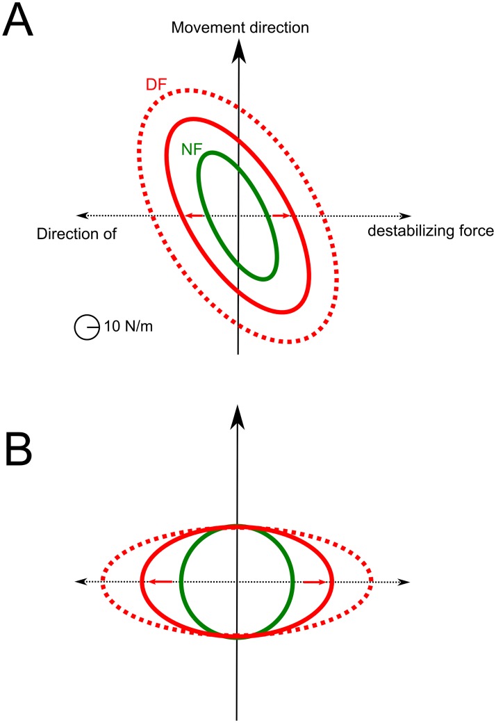
Fig 5. Endpoint stiffness geometry at the midpoint of movement path.
A. Case of the 6-muscles model with detailed results reported in Fig 4. B. Case of a 2-D Cartesian mass-point model. In green, the geometry of the optimal endpoint stiffness without divergent force field (NF) is represented. In red, the same data is reported when the divergent force field is on (DF). Solid lines correspond to β = 40 and dotted lines to β = 80 (note that qvar and σi were fixed in these simulations).

