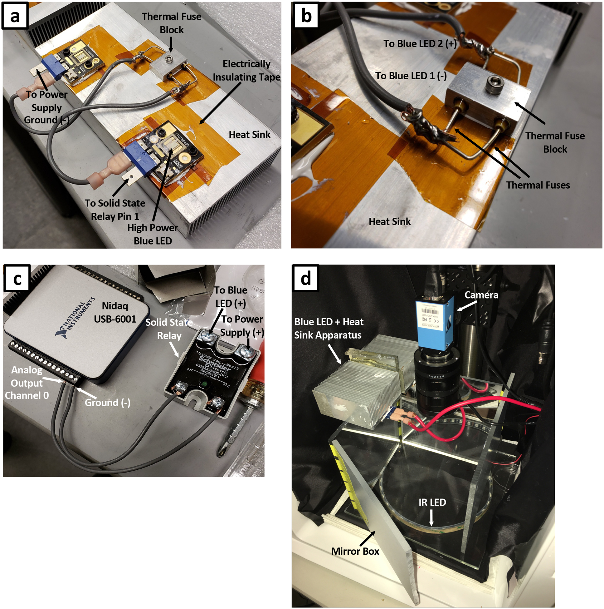
Figure 3. Blue light stimulus assembly.

(a) High power blue LEDs attached to an aluminum heat sink. LEDs are wired in series through a set of thermal fuses. LEDs are electrically isolated from the heat sink using electrical insulating tape. (b) Magnified view of thermal fuse block secured to the heat sink. (c) Electrical connections between NIDAQ I/O device and solid state relay. This assembly allows for computer control of blue LEDs. (d) Complete imaging rig outfitted with blue LED stimulation. An acrylic mirror box is used to generate uniform blue light illumination.
