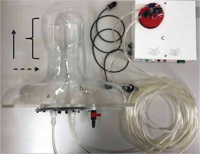
Fig. 3.
Configuration of the flow phantom apparatus. The flow phantom consists of a U-shaped tube with two straight portions connected by a curved portion.The solution flows into segment (a) and out from segment (b). They are connected to the calibrated flow pump (c) that monitors the flow rates. The solid arrow represents the direction of the magnetic field B0. The curly bracket indicates the acquisition volume. The dashed arrow represents the acquisition plane.

