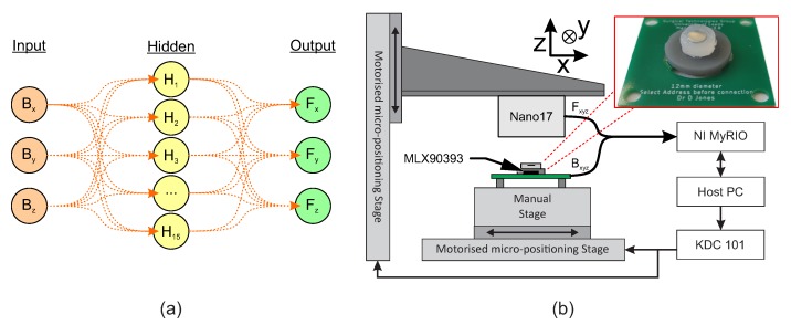
Figure 7.
(a) Structure of the two-layer neural network used in the calibration; and (b) The multi-axis loading test setup , indicating two of the three linear stages used in the calibration. A third stage acts into the plane of the diagram to provide y-axis movement. A real-time measurement device is used to record magnetic field, applied force, and encoded position of the indentor. Inset: The prototype sensor used in calibration with 4 mm magnet embedded.

