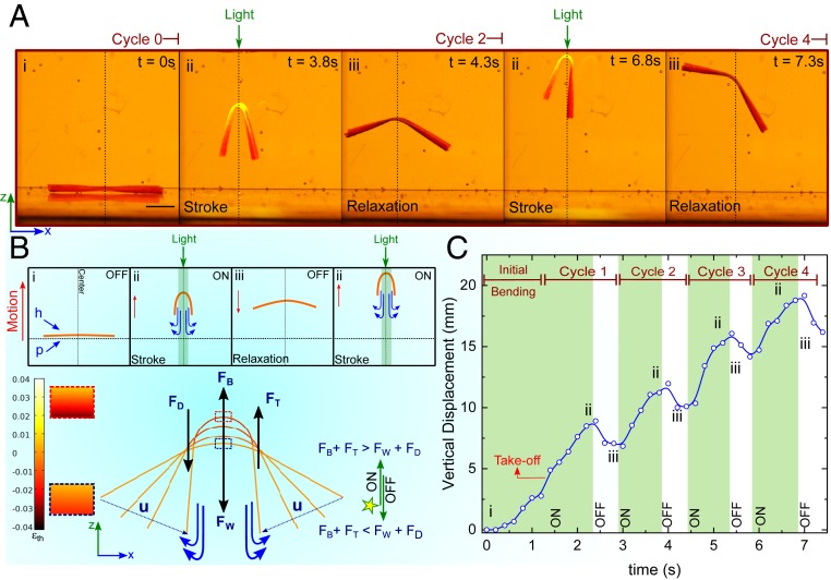
Fig. 6.
Underwater swimming locomotion mode. (A) Swimming of an LCG-70 cantilever construct (16 × 3× 0.1 mm3) in consecutive illumination cycles (ii and iii). The upward locomotion continues until the illumination is able to target the center of the mass. (Scale bar, 4 mm.) (B) The net upward motion is the result of light-induced buoyancy (FB) and the propulsive thrust (FT) during the 1-s period of stroke in state ii. Upon illumination, the two ends of cantilever move toward each other with the speed of u, leading to the downward propulsion of water. When the light is OFF during the 0.5-s period of relaxation, the cantilever does not fully relax in state iii. Time-resolved actuation profiles are obtained by the FE modeling and the thermal strain profile at the stroke and relaxation periods are shown on the left side of the swimmer. The net displacement is positive in the z-direction. (C) Tracking the center part of the LCG-70 construct shows that the initial buoyancy and shape change for the take-off takes place in less than 1.5 s ,followed by vertical swimming with an almost constant velocity of 4.9 mm⋅s−1 during the stroke period. Maintaining a constant light intensity in this experiment was difficult due to the manual control of the distance between the light source and the cantilever. However, the light intensity was always below 1.8 W⋅cm−2. The swimming experiment was done in salt-water brine with a density of 1.03 g⋅cm−3.

