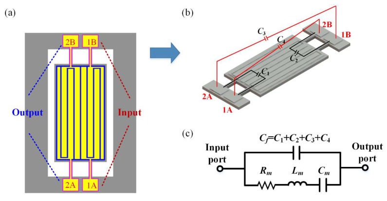
Figure 2.
Schematic of the parasitic capacitive feedthrough in the proposed resonator. (a) Ports 1A and 1B are input ports, and ports 2A and 2B are output ports. The electrodes are divided into two sets: set A and set B. The electrodes in the same set are connected to input and output ports respectively (e.g., 1A and 2A). (b) C1 and C2 are the direct feedthrough between the input and output ports within one set. C3 and C4 are the cross feedthrough between the input and output ports belonging to different sets. (c) Traditional Butterworth-van Dyke (BVD) equivalent circuit model of the proposed resonator.

